



As electrified platforms move to higher battery voltages and more distributed electrical architectures, the role of the DC-DC converter is changing fundamentally. Today’s converters are no longer limited to supplying auxiliary 12V loads. They are becoming active energy management nodes that can control dynamic loads, process regenerative power, and stabilize low voltage networks under ever more challenging conditions.
This evolution is especially visible in high-performance electric vehicles, aerospace systems, motorsport, maritime applications and non-road mobile machinery (NRMM) where the move to 800V+ platforms creates new challenges in terms of efficiency, control bandwidth, electromagnetic compatibility and fault management.
In this context, the partnership between Efficient Power Conversion (EPC) and BrightLoop highlights the evolution of converter design enabled by wide-bandgap devices, not just at the level of the semiconductor, but also in the areas of topology selection, control architecture, thermal engineering, and system integration.
From Auxiliary Converter to Energy Management Node
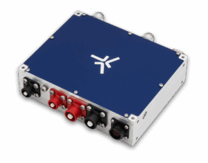
BrightLoop’s latest converter architecture departs significantly from traditional fixed-ratio auxiliary DC-DC converters. Rather than designing a platform around a single voltage ratio, the company developed a configurable bidirectional architecture capable of supporting HV inputs approaching 1 kV, dual low-voltage ports, and high-current bidirectional operation.
The shift was driven by an increasingly fragmented electrification landscape.
“Initially, Brightloop designed fixed-ratio auxiliary converters tailored to specific client applications. However, comprehensive market analysis revealed a recurring industry challenge: diverse voltage architectures across platforms, yet identical fundamental needs for power conversion and management,” said BrightLoop spokeperson. “We recognized that a wide-input, bidirectional topology could address multiple client requirements with a single scalable platform.”
The architectural consequence is substantial. Instead of operating as passive power supplies, these converters actively participate in low-voltage bus stabilization, managing transient current events and reverse regenerative energy flows.
“Transitioning from a unidirectional converter to a bidirectional energy node allowed us to actively stabilize the low-voltage (LV) bus, effectively dampening voltage transients and managing both peak current demands and reverse regenerative currents,” said BrightLoop.
Why Topology Still Matters More Than Devices
Although GaN semiconductors often dominate conversations around efficiency improvements, topology selection remains a defining factor in converter performance.
For high-power HV-LV conversion, BrightLoop adopted a multi-phase interleaved synchronous buck-boost topology designed to preserve efficiency across both step-down and step-up operation.
“Topology efficiency is driven by high-frequency switching and optimized real-time control rather than circuit complexity,” said BrightLoop. “By utilizing a multi-phase interleaved synchronous buck-boost topology, we achieve smooth transitions between buck and boost modes.”
The choice of an interleaved architecture is especially important at low-voltage, high-current operation, where conduction losses increasingly dominate switching losses. Delivering hundreds of amps at the LV side shifts performance bottlenecks toward parasitic resistance and thermal dissipation.
“At high current levels on the LV side, conduction losses and PCB parasitic resistance are the dominant loss mechanisms,” BrightLoop explained. “We implemented a multi-phase interleaved architecture that splits the high total current across parallel buck-boost channels, drastically reducing per-channel losses.”
This distributed current-sharing strategy was combined with parallel low-RDS(on) GaN transistors to reduce conduction losses while maintaining switching efficiency. Although higher switching frequencies typically increase switching losses, operating at 600 kHz enabled smaller magnetic components and lower-DCR inductors, reducing conduction losses and improving thermal performance.
GaN Devices Enable Higher Density and Faster Control
The collaboration with EPC played a central role in enabling BrightLoop’s switching strategy.
Rather than using silicon MOSFETs, BrightLoop selected EPC’s enhancement-mode GaN FETs to support operation at 600 kHz – substantially above the switching frequencies typically associated with comparable high-power silicon converters.
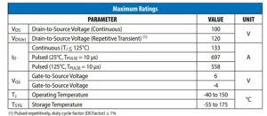
“Our initial selection for this design was the EPC2302,” said BrightLoop. “We chose it for its exceptionally low RDS(on), which is critical for reducing conduction losses at high currents.”
According to BrightLoop, thermal performance was equally important. The thermally enhanced package helped improve heat extraction while the higher breakdown voltage expanded the converter’s safe low-voltage operating range.
The company is now validating EPC2361 devices to further improve power density and reduce conduction losses.
“We are currently validating the EPC2361, which offers an even lower RDS(on), enabling us to achieve higher power density with further reduced losses,” BrightLoop added.
The move to GaN introduced benefits extending far beyond efficiency gains.
“The significant reduction in parasitic capacitances offered by GaN technology compared to traditional Silicon MOSFETs has been a major system-level differentiator,” said BrightLoop. “It enables us to increase the switching frequency from the typical 100–300 kHz range up to 600 kHz and beyond.”
Higher switching frequencies reduce passive component volume, enabling more compact magnetics and higher overall power density. Equally important, faster switching enables tighter digital control loops and significantly improved transient response.
“From a control standpoint, the higher switching frequency provides a much faster dynamic response, allowing the converter to handle transient events with superior bandwidth and agility,” BrightLoop said.
A switching frequency of 600 kHz in conjunction with high-bandwidth real-time digital control ensures stability over extreme conversion ratios. The ultra-fast switching speed enables us to reach a high control loop bandwidth. This enables our digital controller to react dynamically to high dv/dt and di/dt events. This ensures accurate regulation, high transient response and smooth bidirectional transitions with no danger of instability or control saturation.
Co-Engineering Reliability at High dv/dt
Wide-bandgap adoption introduces new challenges alongside its advantages. Faster switching transitions increase dv/dt and di/dt stress, making reliability increasingly dependent on layout parasitics, thermal design, and gate-drive optimization rather than nominal semiconductor ratings alone.
To address this, EPC and BrightLoop collaborated during the design phase rather than after hardware completion.
“Prior to final PCB layout and schematic validation, Brightloop engaged in a collaborative design review with EPC’s engineering team,” BrightLoop explained. “This joint effort focused on optimizing the gate driver circuitry, selecting appropriate magnetic components for high frequency operation, and defining the optimal switching speeds.”
This co-engineering process proved particularly valuable for ensuring robustness under worst-case operating conditions.
“Because device reliability in extreme operating environments is heavily influenced by layout parasitics and thermal dissipation, EPC’s feedback was invaluable in fine-tuning our thermal and electrical margins,” said BrightLoop.
The collaboration also extended into electromagnetic compatibility (EMC) optimization—often one of the most difficult aspects of high-frequency GaN power conversion.
“To manage the high dv/dt and di/dt transitions inherent to fast GaN switching, extensive PCB layout optimization was conducted to minimize parasitic power loop inductance,” BrightLoop explained. “Lowering this loop inductance significantly curtails voltage ringing and electromagnetic radiation.”
BrightLoop employed advanced PCB technologies, including micro-vias and blind vias, to physically isolate high-power switching loops from gate-driver circuitry, minimizing electromagnetic coupling and preserving gate-drive integrity.
Stability in Real Machines, Not Ideal Benches
Laboratory conditions rarely reflect real deployment environments. In electrified vehicles and industrial systems, converters must interact with batteries, long cable harnesses, and dynamic loads capable of introducing instability.
According to BrightLoop, cable parasitics emerged as one of the most important external variables affecting converter behavior.
“The most critical external parameter affecting system stability is the length of the external cables, which introduces significant parasitic line inductance,” the company said. “This inductance, excited by fast current transients, interacts with the system to create LC resonant circuits that generate severe voltage oscillations and ringing.”
To suppress these effects, additional bulk decoupling capacitance becomes essential for damping resonances and stabilizing input and output rails during transient events.
Fault handling also reflects the system-level focus of BrightLoop’s architecture. Rather than entering shutdown during overload or short-circuit events, the converter actively regulates current through an ultra-fast inner control loop.
“The BrightLoop converter does not trigger a shutdown or enter a fault state when a short-circuit or overload occurs,” said BrightLoop. “Instead, it utilizes an ultra-fast inner current limiting loop that actively regulates the current at its maximum allowable limit.”
From the point of view of the control theory, this loop is equivalent to an actuator saturation that limits the output to a safe maximum operating current value, without stopping the conversion process. This prevents the converter from tripping and ensures continuous operation while allowing the system to recover seamlessly as soon as the external fault or overload condition is cleared.
Centralized or Distributed Power?
In the transition to zonal vehicle electrical architectures and higher battery voltages, the role and location of DC-DC conversion is changing too. The system level requirements are expected to have both centralized and distributed high voltage to low voltage conversion strategies co-existing in the system.
In high constrained space and weight applications (e.g. high performance vehicles) centralized power conversion architectures are often preferred to ease packaging and improve power density. For applications such as aerospace, maritime, and heavy-duty transportation, distributed DC-DC converter architectures may be preferred to increase redundancy, improve fault isolation, and support safety-critical low-voltage networks.
The choice of wide-bandgap technologies in DC-DC power conversion is part of a larger engineering trend: optimizing the performance of a system is not just about swapping out silicon devices. The efficient implementation becomes more and more dependent on the co-optimization of semiconductor devices and switching behavior, thermal management, PCB layout, electromagnetic compatibility and control strategies.
With the evolution of electrified systems to higher operating voltages and more dynamic load profiles, DC-DC converters are playing an increasingly important role in overall power architecture, enabling energy distribution, subsystem isolation and power management across the platform.
